ROVEN - Reflow Oven Controller

The Reflow Oven Controller Project
A while ago I searched for a good DIY project to control my Reflow Oven (a fancy name for a conventional kitchen appliance). As you probably know, there are many benefits to using SMD over through-hole components. Some of the advantages are size, cost and time. The smaller size means that the circuit boards can be smaller. The process of putting the solder paste, placing the components and using the reflow oven to solder them all at the same time saves time over traditional through-hole procedure, where you have to solder every component by hand.
I found some excellent projects, but none of them fitted my particular needs. So I decided to make my own.
I made some design decisions early in the life of the project:
- A controller that works in both 120V and 230V countries, using 50/60Hz
- I wanted the control to be as intuitive as possible
- Include many common reflow profiles, and allow for customized ones
- Make the firmware as flexible as possible
- Enable upgrading the firmware without using a programmer (via USB cable)
- Graphical display to show the reflow process
- Temperature output to computer for drawing Excel graphs
- Automatic PID configuration
The project also required a name. After a bit of thinking, I decided to call it ROVEN (an acronym for Reflow Oven).
The Reflow Process
A reflow oven is used to reflow solder SMD parts onto a PCB (Printed Circuit Board). Usually the process consists of applying either a leaded or unleaded solder paste to the pads on the PCB (by using a stencil or just manually). Next, the SMD components are placed on the pads and the PCB is put into the reflow oven. The reflow oven follows a specific thermal profile in order to solder the components to the board. Each stage of reflow process should be followed according to manufacturer instructions. Failure to do so can lead to dysfunctional components, thermal stress or destroy the parts tolerances.
There are 7 stages in my reflow system (Preheat, Soak, Reflow, Dwell, Peak, Keep and Cooling).
Stage 1 – Preheat
At this preheat stage, the PCB is heated gradually in order to bring up the temperature. The temperature inside the reflow oven is raised to approximately 100°C at a rate of approximately 2°C per second.
During this state, the components on the PCB get warmer and solder flux starts to melt and makes the circuit board ready for the next stage.
Heating too quickly can cause defects such as components to crack and the solder paste to splatter causing solder balls during reflow.
Stage 2 – Soak
The temperature is slowly raised to approximately 130°C – 170°C and maintained for approximately 60-120 seconds. At this stage, the temperature of the circuit board and components are nearly the same. Equalizing the temperature prevents cracking or warping of the PCB and/or components during soldering. In addition, the solder flux liquefies and coats the pads.
Care needs to be taken not to have an excessive soak temperature or time as this may result in the flux becoming exhausted.
Stage 3 – Reflow
The temperature inside the oven is ramped up to the melting temperature of approximately 183°C (for leaded paste) . At this stage, the grains of solder begin to melt and bond the metal contacts of the components to the solder pad.
Stage 4 – Dwell
The soldering temperature is quickly raised to approximately 230°C and maintained for approximately 20-45 secs. The solder is now melted and drawn together by surface tension. The flux is pushed outwards by the surface tension leaving behind a bond between the component and the solder pad.
Stage 5 – Peak
The soldering temperature is raised to the highest temperature for the paste (235°C) and maintained for approximately 20 secs.
Stage 6 – Keep
The soldering temperature is cooled down to the melting point of the paste (183°C ) over a period of approximately 30 seconds. This starts the gradual colling of the solder paste.
Stage 7 – Cool Down
The temperature inside the oven is slowly decreased to the room temperature. The cool down must take place slowly to prevent potential warping or cracking of the components and/or PCB because of thermal shock. It is important to not cool the assembly too rapidly - usually the recommended rate of cooling should not exceed 3ºC/second.
The below figure shows a typical temperature vs. time curve for the reflow process:
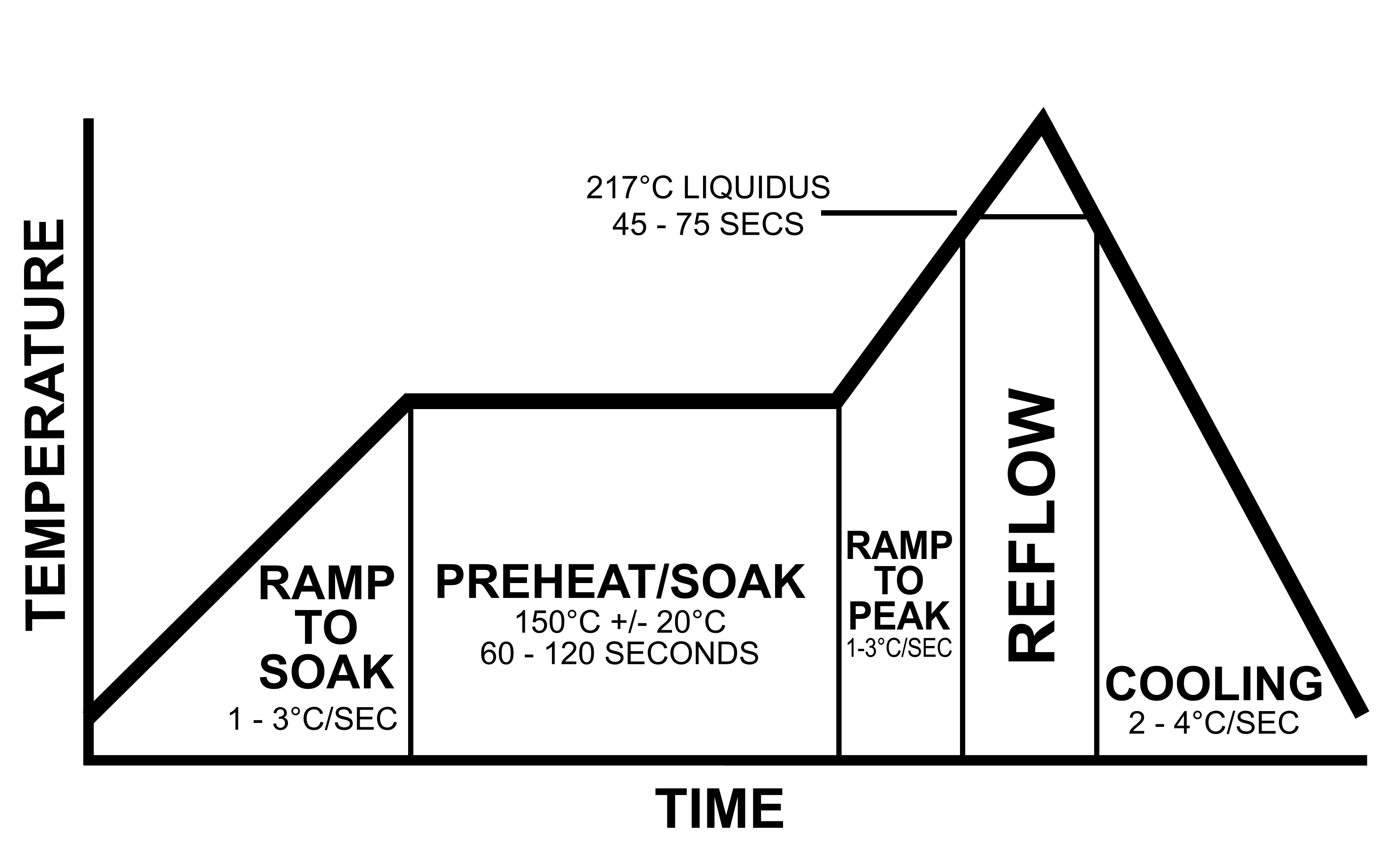
The actual time and temperature requirements is dependent on the type of solder paste used. For a typical Sn63/Pb37 (tin/lead) solder paste, the recommended reflow profile is below:

In general, solder pastes can be divided into two groups based on the composition of the solder. Most lead based solder pastes consist of an allow of tin (Sn) and lead (Pb). This composition has a melting point of 183°C.
Lead-free pastes usually consist of a tin (Sn), silver (Ag) and copper (Cu) alloy. Lead-free solder paste begins to melt around 217°C with a maximum reflow temperature of 235-240°C. Current Restriction of Hazardous Substances (RoHS) regulations require consumer electronics to contain lead-free solder (some exceptions apply).
What is PID?
PID stands for “Proportional, Integral and Derivative.” Together, these three terms describe the basic elements of a PID controller. A PID controller is a type of control loop feedback system that calculates the difference between a measured input variable and a desired set point and attempts to minimize the error (how far are we away from set point) by adjusting the systems output.
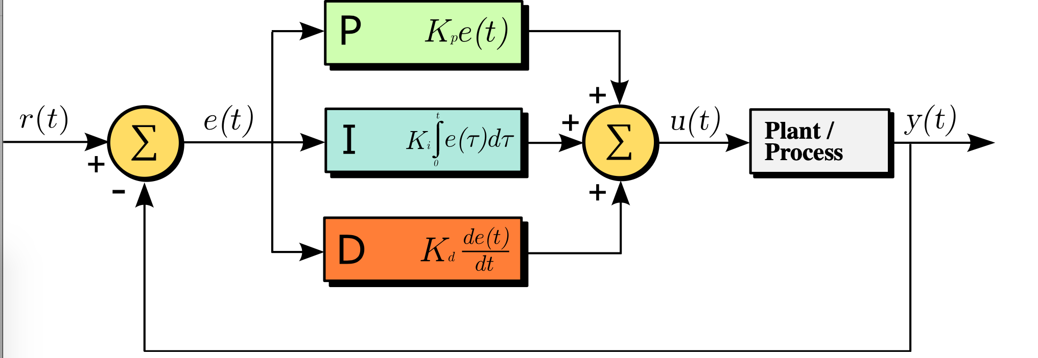
What is Proportional Control?
The proportional term adds or subtracts output proportional to the current error value of the control system in order to drive the system back to the desired output (set point). The error value is given by how far the input (measured value) is away from the set point.
What is Integral Control?
A proportional only system would not be sufficient enough to eliminate the error. The system must be able to change its output according to the current error as well as past errors. The integral is proportional to both the magnitude (amount) of the error and the duration of the error. In other words, the integral is the sum of errors over time. This means the integral adds the amount of error as time passes and attempts to rapidly change the output to eliminate the error.
The integral component tracks accumulated error and attempts to accelerate the process towards the set point. This can cause the process to overshoot the set point if not kept in check.
What is Derivative Control?
The derivative term measures how quickly error changes with respect to time and affects the rate of change of the controller output. The rate of change is equivalent to measuring the slope of a line. The derivative term will attempt to reduce the magnitude of the overshoot that tends to be produced by the integral component.
Schematic
This is a modular design so I’ll pick each part individually and explain it. Here’s the full schematic.
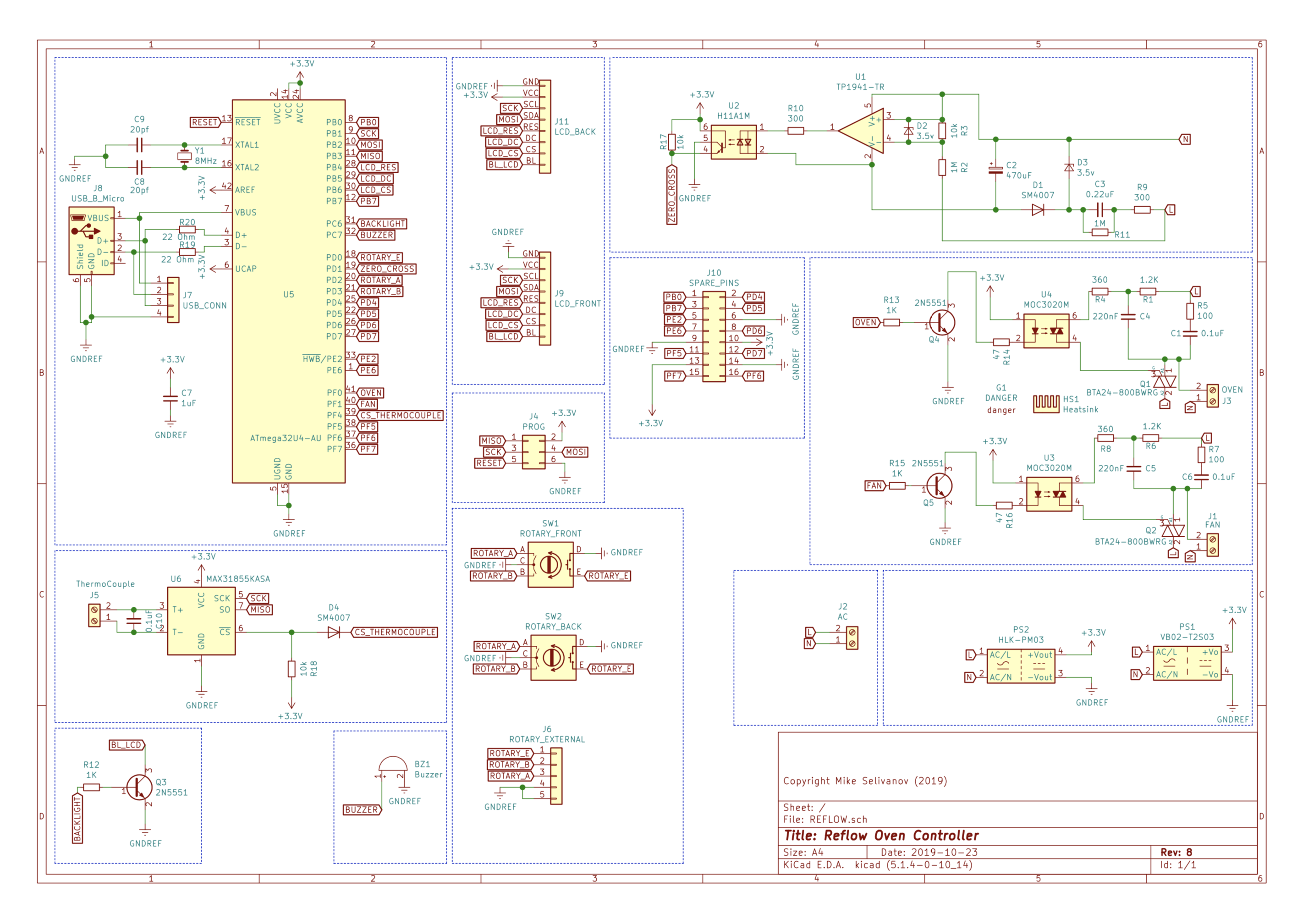
The design is suitable for countries with both 110v/120v and 220-230v 50/60Hz. The controller automatically detects the frequency and uses the correct timing for the TRIACs .
The TRIACs
Oven and Fan use identical circuits.
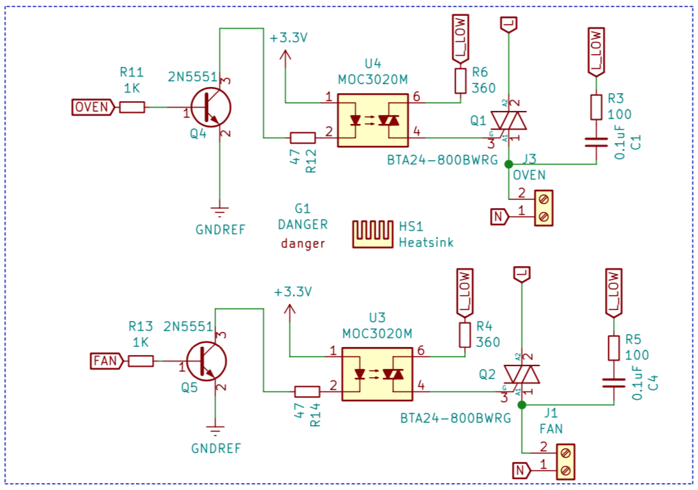
The maximum current rating for this design is 16A (limited by the terminal connectors). The TRIACs are oversized and support up to 25A. This gives a nice margin of safety. The TRIAC controls when these terminals are switched on and off.
The TRIAC is a development of the thyristor. While the thyristor can only control current over one half of the cycle, the triac controls it over two halves of an AC waveform.
As such the triac can be considered as a pair of parallel but opposite thyristors with the two gates connected together and the anode of one device connected to the cathode of the other, etc.. It is electronically controlled semiconductor that, when activated, can conduct current through it in either direction. This bi-directionality makes it a good choice for using a small DC control signal to switch a large AC mains supply on and off. This makes it an ideal solution for an electronic switch for AC.
A key feature is that once a TRIAC is activated (latched) it will stay latched on until the AC sine wave crosses zero again. If we combine this feature with a zero-crossing detector then it becomes a simple matter of timing to ‘dim’ an AC wave by chopping it off at the same point in each half-cycle.
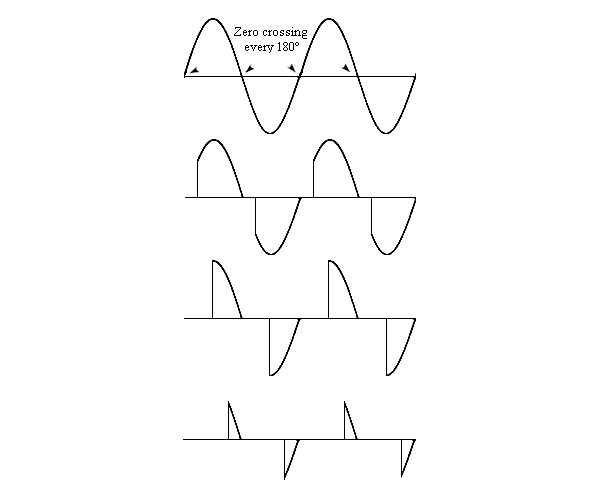
The diagram above shows an example of how AC dimming is achieved. You detect when the wave crosses zero, then you wait some period of time depending on how little or how much dimming you want and then you switch on the TRIAC. The TRIAC will then stay switched on (latched) until the next zero crossing at which point you start again.
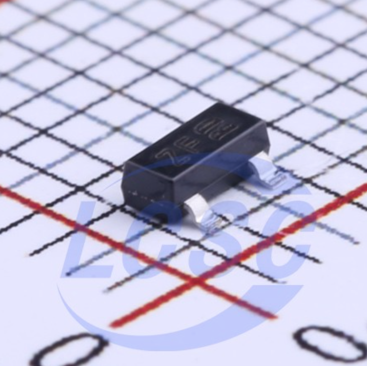
It’s important to choose a TRIAC that’s rated in excess of the maximum planned current so that it can handle the inrush current surge that happens when the oven first switches on. I rate this controller for 16A load so I’ve chosen BTA24-600BWRG 25A/600v TRIAC (I’m actually using a cheaper substitute named JST26Z-600BW).
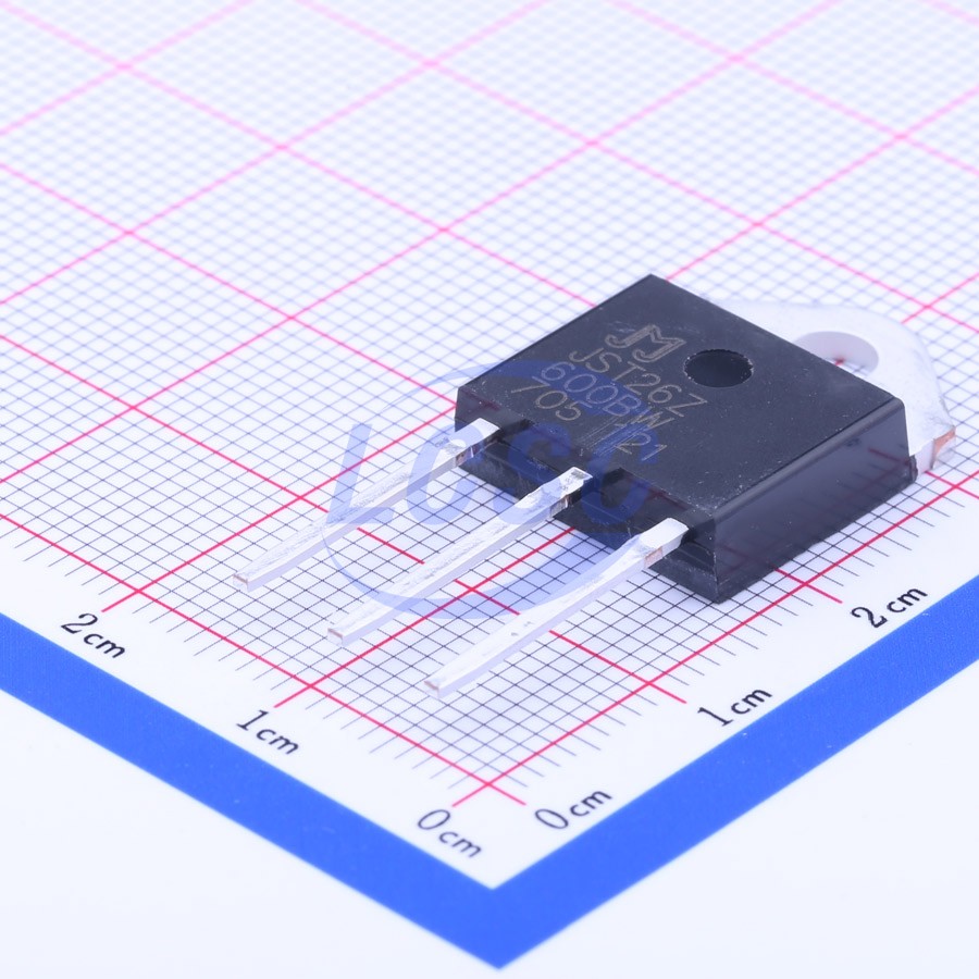
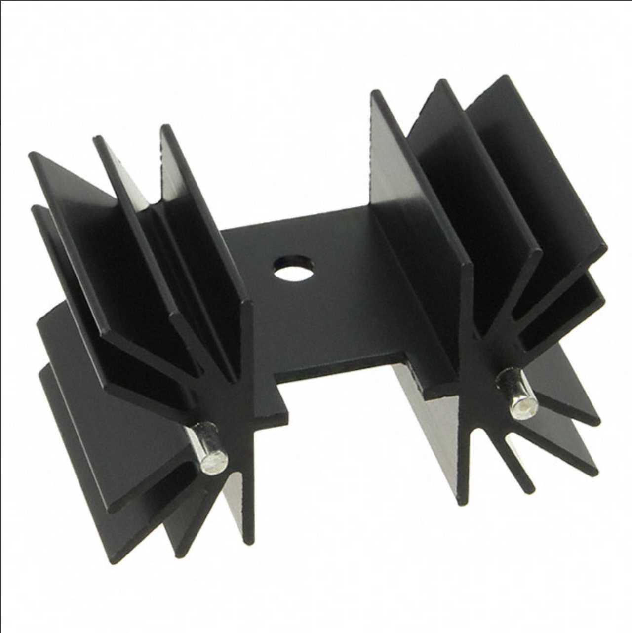
The TOP3 package can be cooled in accordance with the rating of the TRIAC. A TRIAC of this size will typically come in a TO-220 or TOP3 package and it will get hot during use so an appropriately rated heatsink is required.
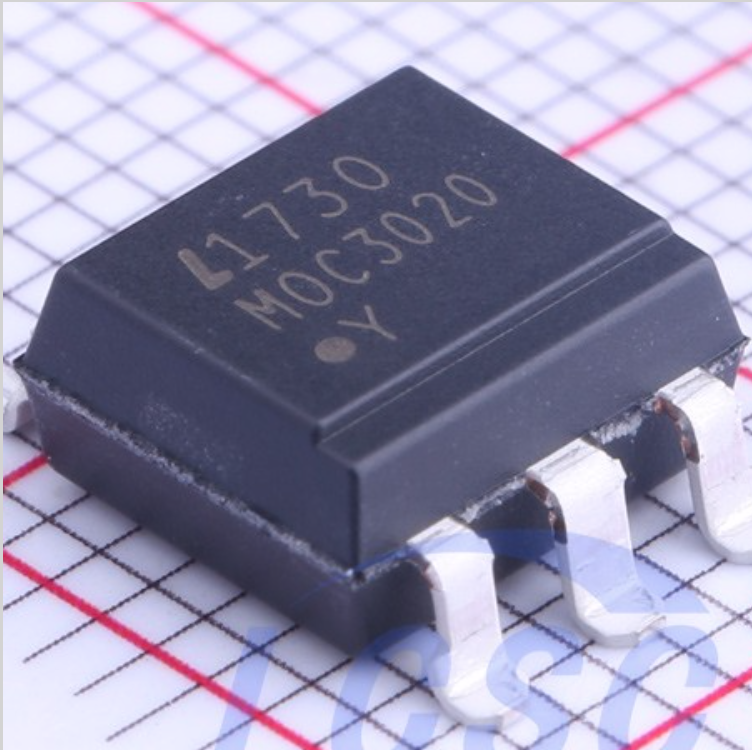
I use a MOC3020S (SMD version of MOC3020M) TRIAC optocoupler to control the TRIAC’s gate and the driving circuit is taken from the MOC3020 datasheet. A snubber is used to prevent false triggering of the TRIAC when the load being driven has an inductive component such as the fan on the oven that I’m using.
The MOC3020 requires between 30 and 60mA to switch on. This is too much to drive directly from the pin of an MCU so I’m using the 2N5551 transistor to drive it.
Triac thermal considerations
As I mentioned, TRIAC requires a heatsink. Heatsinks are rated in °C/W which tells you how many degrees they will rise above ambient per Watt of thermal energy that you ask them to dissipate.
The data sheet provides a nice graph showing the power dissipation of the TRIAC:
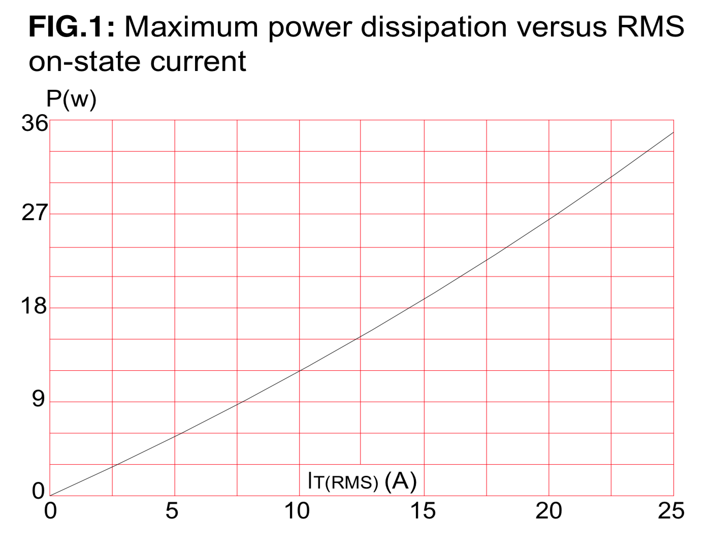
So for 230V / 2KW load the current is 8.7A. Looking at the graph the dissipated power is approximately 10W.
The TRIAC datasheet mentions the Junction-to-ambient temperature, which shows the temperature rise without a heatsink. It is 50°C/W for the BTA24 TOP3 package which means that without heatsink the temperature will rise to 50 * 10W = 500°C. This definetly requires a heatsink.
The heatsink
Tj is the TRIAC’s junction temperature and it must be kept below the maximum value specified in the datasheet: 125°C for the BTA24, and in practice we need to stay well below that value due to the error margin between the theoretical thermal calculations and real life.
AN10384 (https://www.farnell.com/datasheets/1760767.pdf) gives us the equation that we need to calculate the junction temperature for the power dissipation that we determined (10W).
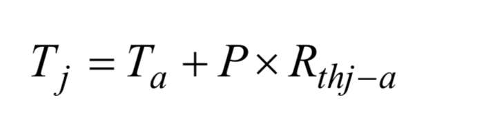
Ta is the ambient temperature (°C) and Rthj−a is the junction-to-ambient thermal resistance (°C/W).
Thermal resistance, like electrical resistance, can be broken down into several smaller resistances connected in series. The TOP-3 package used by the BTA24 has the following resistance model:
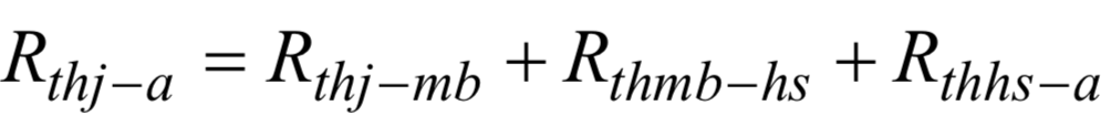
Rth j-mb is the thermal resistance of the junction to mounting base. The value is quoted in the datasheet as 0.8°C/W .
Rth mb-hs is the resistance between the mounting base of the TOP3 and the heatsink. This will vary depending on whether the package is screwed or clipped to the heatsink and whether or not thermal grease is used. I am screwing the TOP3 to the heatsink and I will use thermal grease. AN10384 quotes a typical value of 0.5°C/W for this method.
Rth hs-a is the resistance between the heatsink and ambient and will be quoted by the manufacturer. If I assume that I don’t want the junction temperature higher than 100°C then the maximum heatsink thermal resistance would be ((100 - 25) / 10) - 0.8 - 0.5 = 6.2°C/W.
I searched through the range of TOP-3 heatsinks and found that Ohmite RA-T2X-25E (41.6mm x 25.4mm x 25mm) offers a thermal resistance of 4.8°C/W in a nice small package.
This heatsink allows for a maximum current of (100 - 25) / (4.8 + 0.5 + 0.8) = 12.3A. This is continuous current. For 230v, that would be operating a 2.8KW oven at 100% power. For 120V, that’s 1.48KW.
XSD366-094 is an alternative from LCSC. The manufacturer does not provide thermal resistance, but the heatsink is slightly wider (45mm x 25mm x 25mm), so it should perform even better.
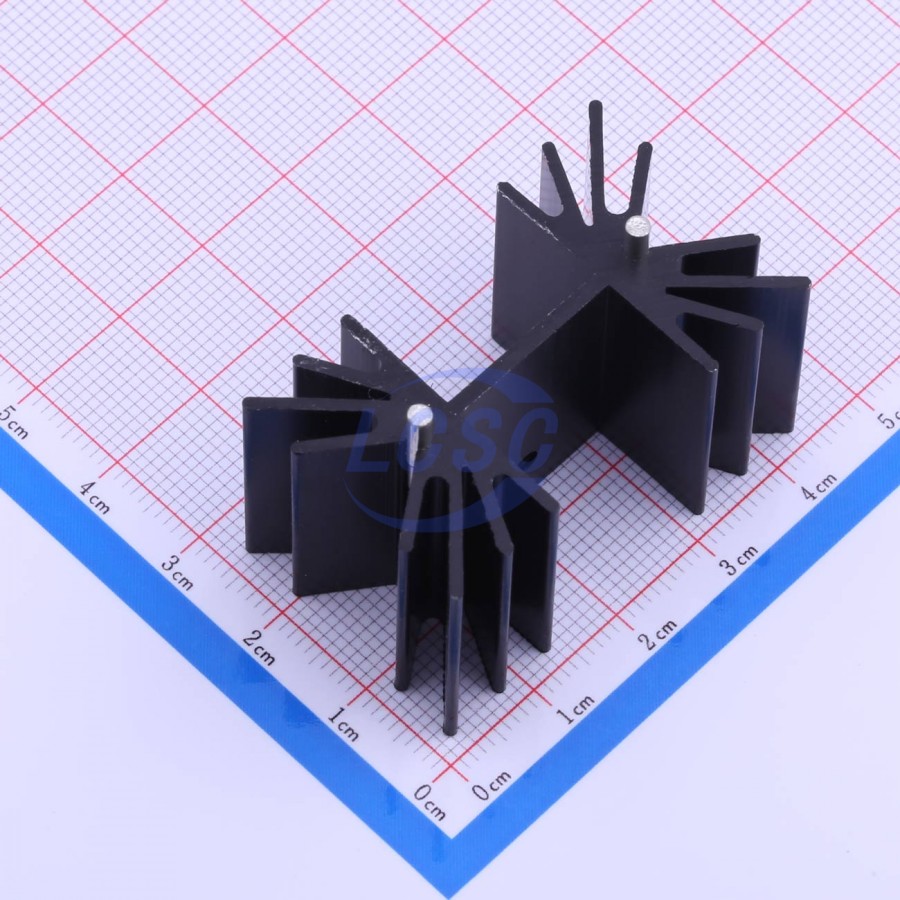
Using my 2KW oven (230v), the heatsink doesn’t even get warm after a full reflow cycle.
The AC-DC transformer
I decided to use an AC-DC isolated power supply to step down the mains voltage to a safe level (3.3V) for the low side of the board. Transformer-less designs for powering MCUs from the mains do exist and are cheaper to build but they are not as safe.
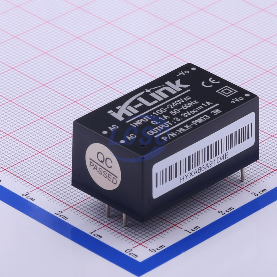
The HLK-PM03 steps down a 100-240VAC input to a 3.3V DC output with full isolation protection.
The mains connector
The mains connector is a 2-way 5.00mm screw terminal. The data sheet rates the connector at 16A.
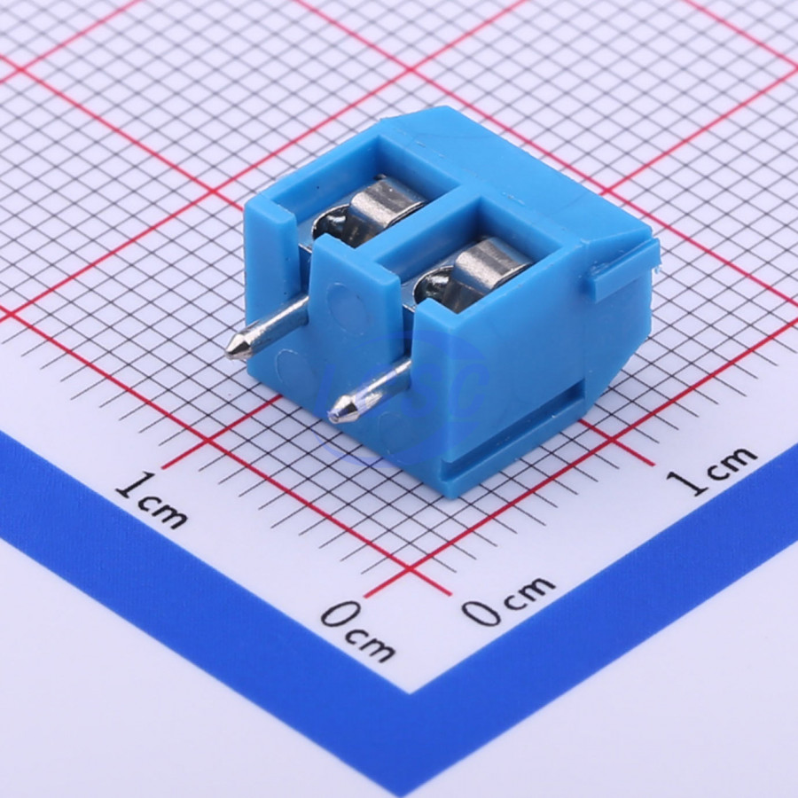
Two pins are provided for 120/240VAC live and neutral. Two similar pins are provided for the oven output and two more pins are provided for the fan.
The zero crossing circuit
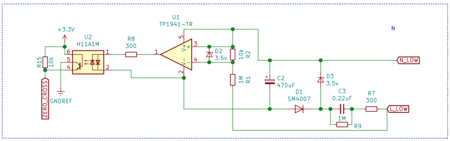
The zero crossing circuit consists of capacitive transformerless power supply (based on Microchip app note 00954A) and zero cross detector (based on TI app note SNOA999) .
The power supply provides 3.3V to rail-to-rail comparator unit, which drives the optocoupler (H11A1M).
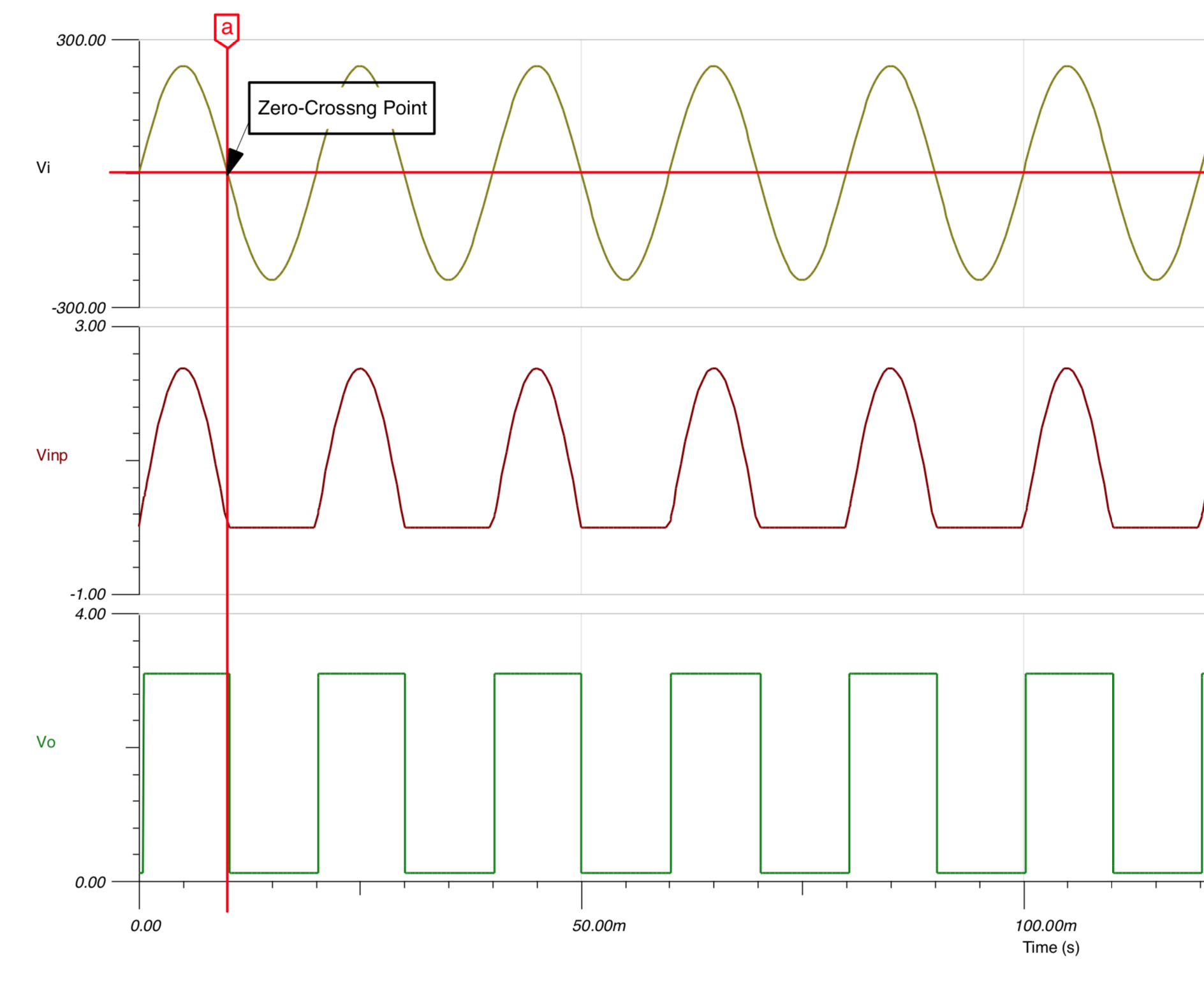
The comparator generates a square signal centered on zero-crossing points. MCU interrupt fires on RISING and FALLING signal.
The comparator used is 3PEAK TP1941-TR model. It's pin-compatible with Microchip MCP-6561T-E and ON Semicondictor NCS2250SN2T1G (although I haven't tested it).
The low-side of the board
The thermocouple IC
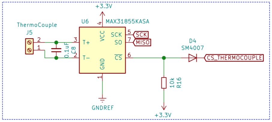
I’m using MAX31855 IC that enables to measure K-type thermocouples. It uses a simple SPI protocol.
The 100nF capacitor is there to clean the signal before it gets to the MAX31855. Maxim recommends the use of the capacitor in their datasheet and according to experience, you will get severe noise problems if you choose to omit it.
The pull-up resistor and the diode are there to enable ISP programming (when chip is reset, the chip enable line goes up, disabling the chip output).
The microcontroller
When I started this project I only had one MCU vendor in mind - Atmel. They’re widely available, affordable, and thanks to the popularity of the Arduino platform there's a lot of material and people familiar with the platform.
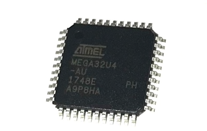
I need to interface the MCU with USB out so the actual processor that I’ve chosen is the ATmega32U4 running at 3.3V and 8Mhz. Since the MAX31855 requires 3.3V, that's the voltage I chose for the DC side. ATmega32U4 is only rated to run at 8MHz at this voltage (it can run at 16MHz at voltages > 3.6V).
As you can see from the schematic I’ve selected an external crystal with 20pF load capacitors for the system clock source even though the ATmega32U4 has an internal oscillator that can run at 8MHz.
The reason for this choice is that I need to provide hi-speed USB communication. I also need to accurately track time over a reflow program so I decided to play safe and install an external crystal.
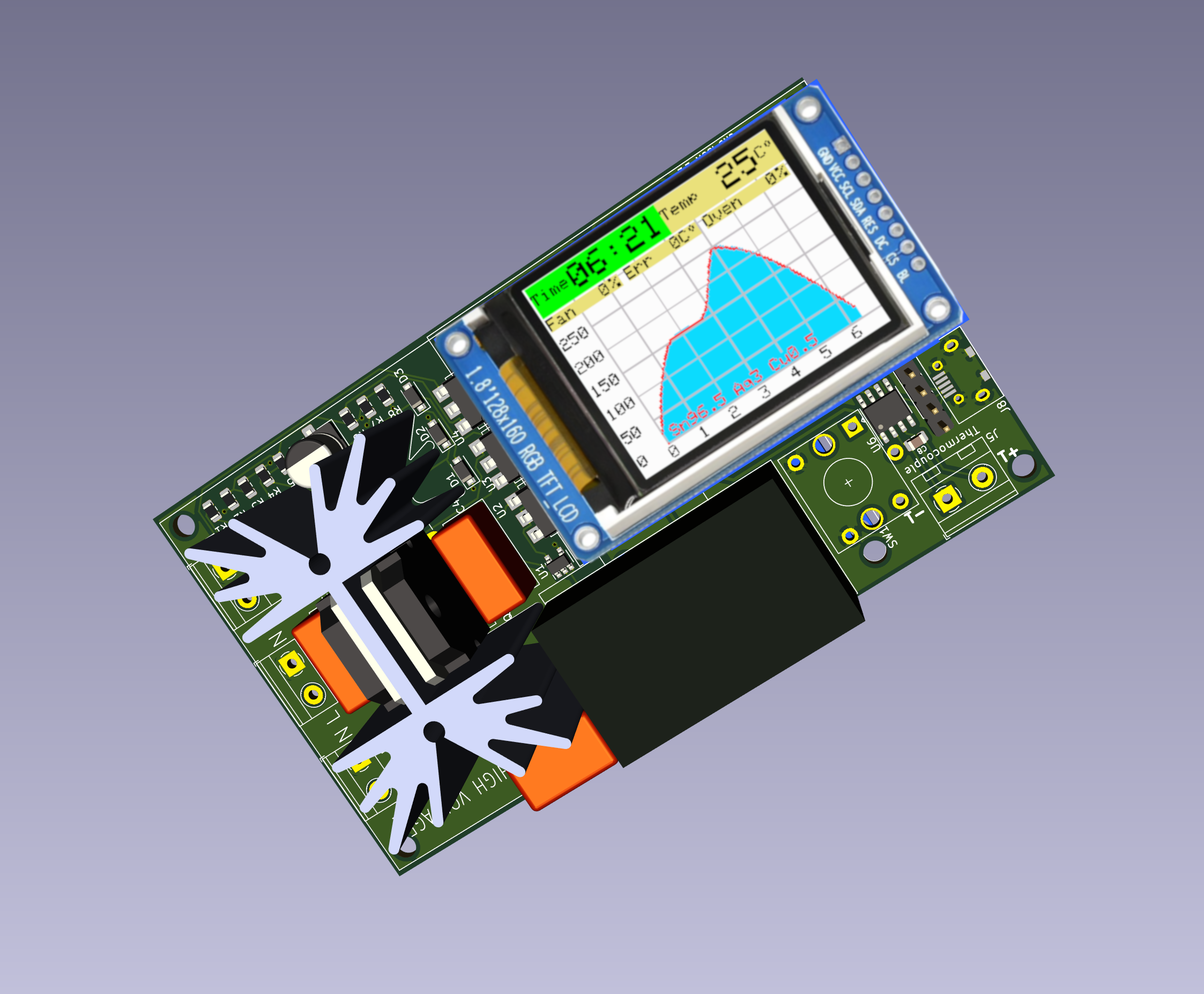
The 1.8 SPI TFT LCD
I decided to add a small and cheap LCD to the design as a main interface. With the addition of a clickable rotary encoder the entire process, including configuration and reflow, is operated from this LCD.
The LCD is 128x160 pixels and can display 65K colors.
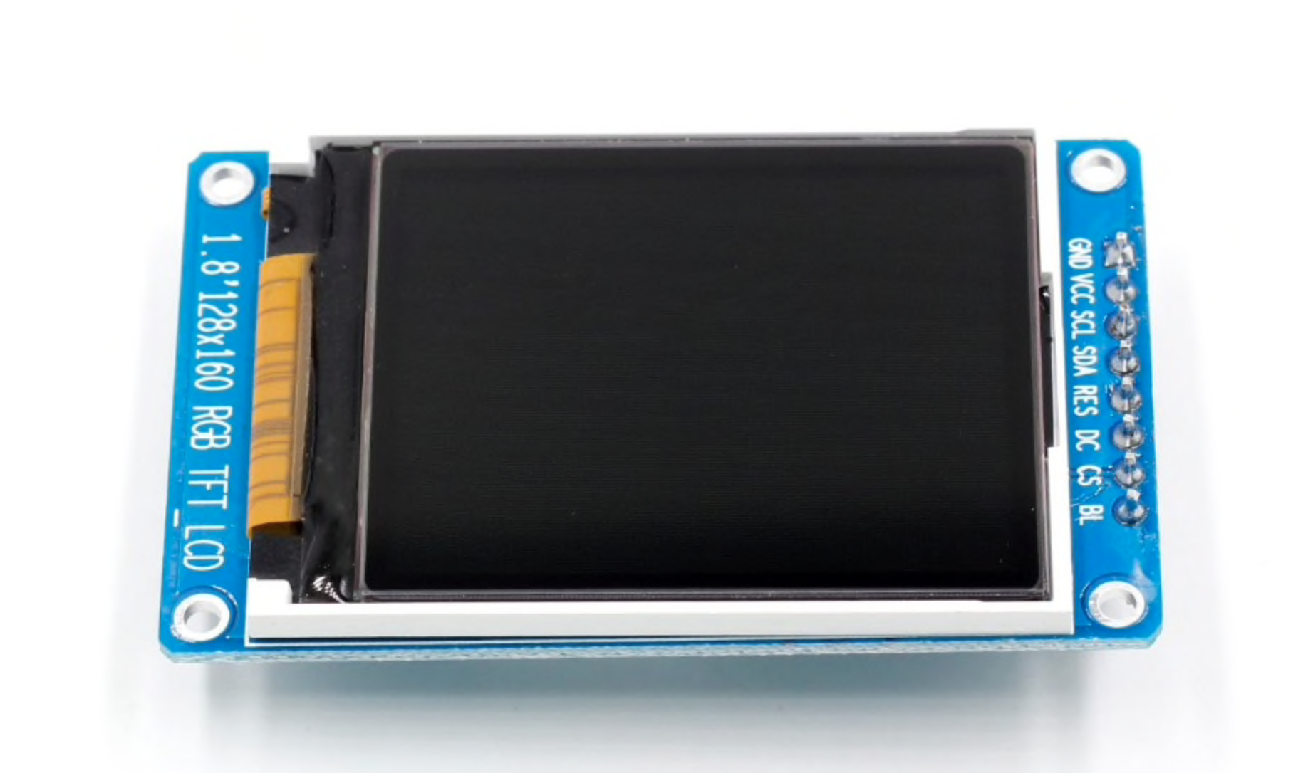
The photograph shows the LCD that I bought on Aliexpress (LCD). Do note pinout of your LCD should be identical to mine, if you want to connect it directly to the board.
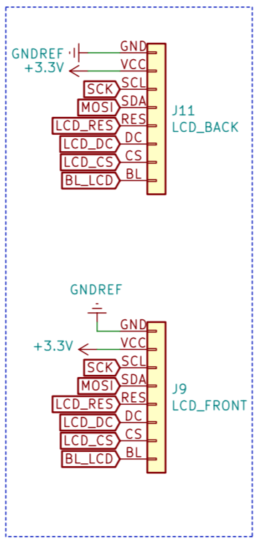
As you can see from the schematic I’m applying a PWM waveform to a transistor to set the backlight brightness in the assumption that the ‘BL’ pin is an input to VCC.
There are two headers on the board for LCD - one on the front and one on the back of the board. You can connect the LCD to either of them, or, alternatively, use some wires to connect the LCD externally.
The rotary encoder
The clickable rotary encoder is used to navigate all the menus.
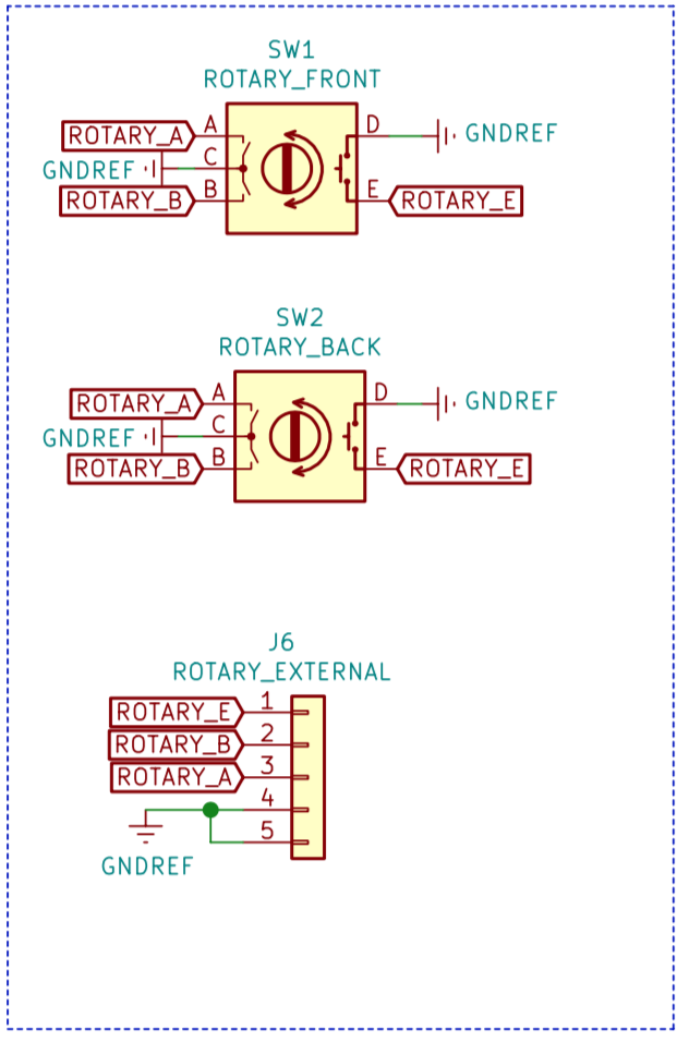
I added front and back options for mounting the rotary encoder on the PCB. There is also a header if you want to connect it using external wires.
The buzzer
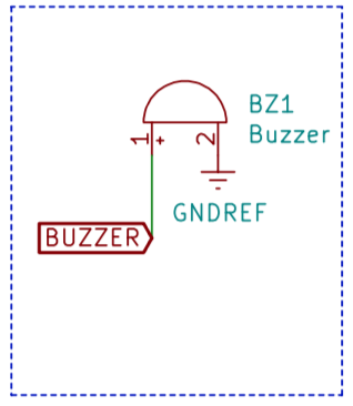
I decided to add a buzzer, so you're notified on your clicks, as well as on the end of the reflow cycle.
The spare pin header
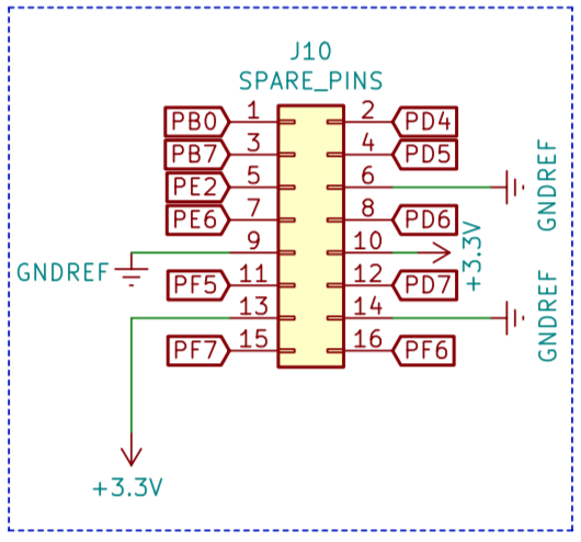
Usused pins are routed to the 2x8 header, so you can connect external components, such as relays, leds or any GPIO device. I also provided GND and 3.3V for convenience.
The pins are marked on the silkscreen.
Bill of materials
Here’s a table that contains the bill of materials for this project. I got nearly all the parts from LCSC (except for the LCD) and have included their part number for easy reference.
LCSC Part Number | Description | Order Qty. | Product Link |
C118173 | M3*15+6 Studs RoHS | 10 | https://lcsc.com/product-detail/Studs_HIWA-C118173_C118173.html |
C358687 | Through Hole,P=2.54mm Pin Header & Female Header RoHS | 20 | https://lcsc.com/product-detail/Pin-Header-Female-Header_MINTRON-MTP125-1105S1_C358687.html |
C25315 | 47 ±5% 1/8W 0805 Chip Resistor - Surface Mount RoHS | 100 | https://lcsc.com/product-detail/Chip-Resistor-Surface-Mount_Uniroyal-Elec-0805W8J0470T5E_C25315.html |
C316764 | 360 ±5% 1/4W 0805 Chip Resistor - Surface Mount RoHS | 50 | https://lcsc.com/product-detail/Chip-Resistor-Surface-Mount_KOA-Speer-Elec-RK73B2ATTD361J_C316764.html |
C316763 | 300 ±5% 1/4W 0805 Chip Resistor - Surface Mount RoHS | 50 | https://lcsc.com/product-detail/Chip-Resistor-Surface-Mount_KOA-Speer-Elec-RK73B2ATTD301J_C316763.html |
C276224 | 22 ±1% 1/4W 0805 Chip Resistor - Surface Mount RoHS | 50 | https://lcsc.com/product-detail/Chip-Resistor-Surface-Mount_KOA-Speer-Elec-RK73H2ATTD22R0F_C276224.html |
C276217 | 1M ±1% 1/4W 0805 Chip Resistor - Surface Mount RoHS | 50 | https://lcsc.com/product-detail/Chip-Resistor-Surface-Mount_KOA-Speer-Elec-RK73H2ATTD1004F_C276217.html |
C65114 | P=2.54mm Pin Header & Female Header RoHS | 20 | https://lcsc.com/product-detail/Pin-Header-Female-Header_Boom-Precision-Elec-C65114_C65114.html |
C350308 | Through Hole,P=2.54mm Pin Header & Female Header RoHS | 5 | https://lcsc.com/product-detail/Pin-Header-Female-Header_HOAUC-2685Y-108CNG1SNA01_C350308.html |
C408907 | 1uF 10V 0805 Multilayer Ceramic Capacitors MLCC - SMD/SMT RoHS | 50 | https://lcsc.com/product-detail/Multilayer-Ceramic-Capacitors-MLCC-SMD-SMT_YAGEO-CC0805KKX5R6BB105_C408907.html |
C94472 | 20pF 50V 0805 Multilayer Ceramic Capacitors MLCC - SMD/SMT RoHS | 50 | https://lcsc.com/product-detail/Multilayer-Ceramic-Capacitors-MLCC-SMD-SMT_Guangdong-Fenghua-Advanced-Tech-0805CG200J500NT_C94472.html |
C64898 | 1kV 1A 1.1V @ 1A SOD-123FL Diodes - General Purpose RoHS | 50 | https://lcsc.com/product-detail/Diodes-General-Purpose_MDD-Microdiode-Electronics-SM4007PL_C64898.html |
C112669 | NPN 600mA 160V SOT-23(SOT-23-3) Transistors (NPN/PNP) RoHS | 20 | https://lcsc.com/product-detail/Transistors-NPN-PNP_KEC-Semicon-2N5551S-RTK-P_C112669.html |
C155445 | 1.8V ~ 5.5V SOT-23-5 Analog Comparators RoHS | 1 | https://lcsc.com/product-detail/Analog-Comparators_3PEAK-TP1941-TR_C155445.html |
C212800 | SOD-123F Zener Diodes RoHS | 20 | https://lcsc.com/product-detail/Zener-Diodes_DIOTEC-BZT52C3V3_C212800.html |
C216454 | 220nF ±10% Through Hole,P=10mm Suppression Capacitors RoHS | 10 | https://lcsc.com/product-detail/Suppression-Capacitors_WQC-C50Q3224KC3L230210_C216454.html |
C129480 | 470uF ±20% 10V SMD,6.3x7.7mm Aluminum Electrolytic Capacitors - SMD RoHS | 10 | https://lcsc.com/product-detail/Aluminum-Electrolytic-Capacitors-SMD_Semtech-CK1A471M-CRE77_C129480.html |
C263688 | 100nF ±10% Through Hole,P=10mm Suppression Capacitors RoHS | 10 | https://lcsc.com/product-detail/Suppression-Capacitors_CHAMPION-SMQP104K310XXC3B1015_C263688.html |
C112349 | Through Hole Coded Rotary Switches RoHS | 1 | https://lcsc.com/product-detail/Coded-Rotary-Switches_ALPS-Electric-EC12D1524403_C112349.html |
C115464 | SMD-6 Triac Optocouplers RoHS | 2 | https://lcsc.com/product-detail/Triac-Optocouplers_Lite-On-MOC3020S-TA1_C115464.html |
C78589 | SMD-6 Optocouplers RoHS | 1 | https://lcsc.com/product-detail/Optocouplers_Everlight-Elec-H11L1S-TA_C78589.html |
C52028 | SO-8 Sensor Interface ICs RoHS | 1 | https://lcsc.com/product-detail/Sensor-Interface-ICs_Maxim-Integrated-MAX31855KASA-T_C52028.html |
C10418 | SMD USB Connectors RoHS | 5 | https://lcsc.com/product-detail/USB-Connectors_Jing-Extension-of-the-Electronic-Co-C10418_C10418.html |
C114504 | Two-way thyristor 600V TO-3P Thyristors - TRIACs RoHS | 2 | https://lcsc.com/product-detail/Thyristors-TRIACs_Jiangsu-JieJie-Microelectronics-JST26Z-600BW_C114504.html |
C259040 | 8MHz ±20ppm HC-49SMD SMD Crystal Resonators RoHS | 5 | https://lcsc.com/product-detail/SMD-Crystal-Resonators_ZheJiang-East-Crystal-Elec-C08000J060_C259040.html |
C94599 | Magnetic NO 2700Hz 3.6V 2.5 ~ 4.5V 8.5mm x 8.5mm 8.5*8.5*3mm Buzzers RoHS | 1 | https://lcsc.com/product-detail/Buzzers_Jiangsu-Huaneng-Elec-MLT-8530_C94599.html |
C209904 | Through Hole Power Module AC-DC RoHS | 1 | https://lcsc.com/product-detail/Power-Module-AC-DC_HI-LINK-HLK-PM03_C209904.html |
C286227 | 42x25x25mm Heat Sinks RoHS | 1 | https://lcsc.com/product-detail/Heat-Sinks_XSD-XSD366-094_C286227.html |
C395882 | P=5.0mm Screw terminal RoHS | 5 | https://lcsc.com/product-detail/Screw-terminal_DIBO-DB301V-5-0-2P_C395882.html |
C44854 | QFP-44_10x10x08P ATMEL & AVR RoHS | 1 | https://lcsc.com/product-detail/ATMEL-AVR_Microchip-Tech-ATMEGA32U4-AU_C44854.html |
C58585 | 1M ±1% 1/2W Axial Metal Film Resistor (TH) RoHS | 50 | https://lcsc.com/product-detail/Metal-Film-Resistor-TH_Uniroyal-Elec-MFR0S2F1004A20_C58585.html |
C385493 | 300 ±1% 1/2W Axial,2.4x6.5mm Metal Film Resistor (TH) RoHS | 50 | https://lcsc.com/product-detail/Metal-Film-Resistor-TH_TyoHM-RN1-2WS300ΩFT-BA1_C385493.html |
C58588 | 100 ±1% 1/2W Axial Metal Film Resistor (TH) RoHS | 100 | https://lcsc.com/product-detail/Metal-Film-Resistor-TH_Uniroyal-Elec-MFR0S2F1000A20_C58588.html |
C111496 | 100nF 50V 0805 Multilayer Ceramic Capacitors MLCC - SMD/SMT RoHS | 100 | https://lcsc.com/product-detail/Multilayer-Ceramic-Capacitors-MLCC-SMD-SMT_YAGEO-CC0805ZRY5V9BB104_C111496.html |
C160065 | 1K ±1% 1/4W 0805 Chip Resistor - Surface Mount RoHS | 100 | https://lcsc.com/product-detail/Chip-Resistor-Surface-Mount_KOA-Speer-Elec-RK73H2ATTD1001F_C160065.html |
C159912 | 10K ±5% 1/4W 0805 Chip Resistor - Surface Mount RoHS | 100 | https://lcsc.com/product-detail/Chip-Resistor-Surface-Mount_KOA-Speer-Elec-RK73B2ATTD103J_C159912.html |
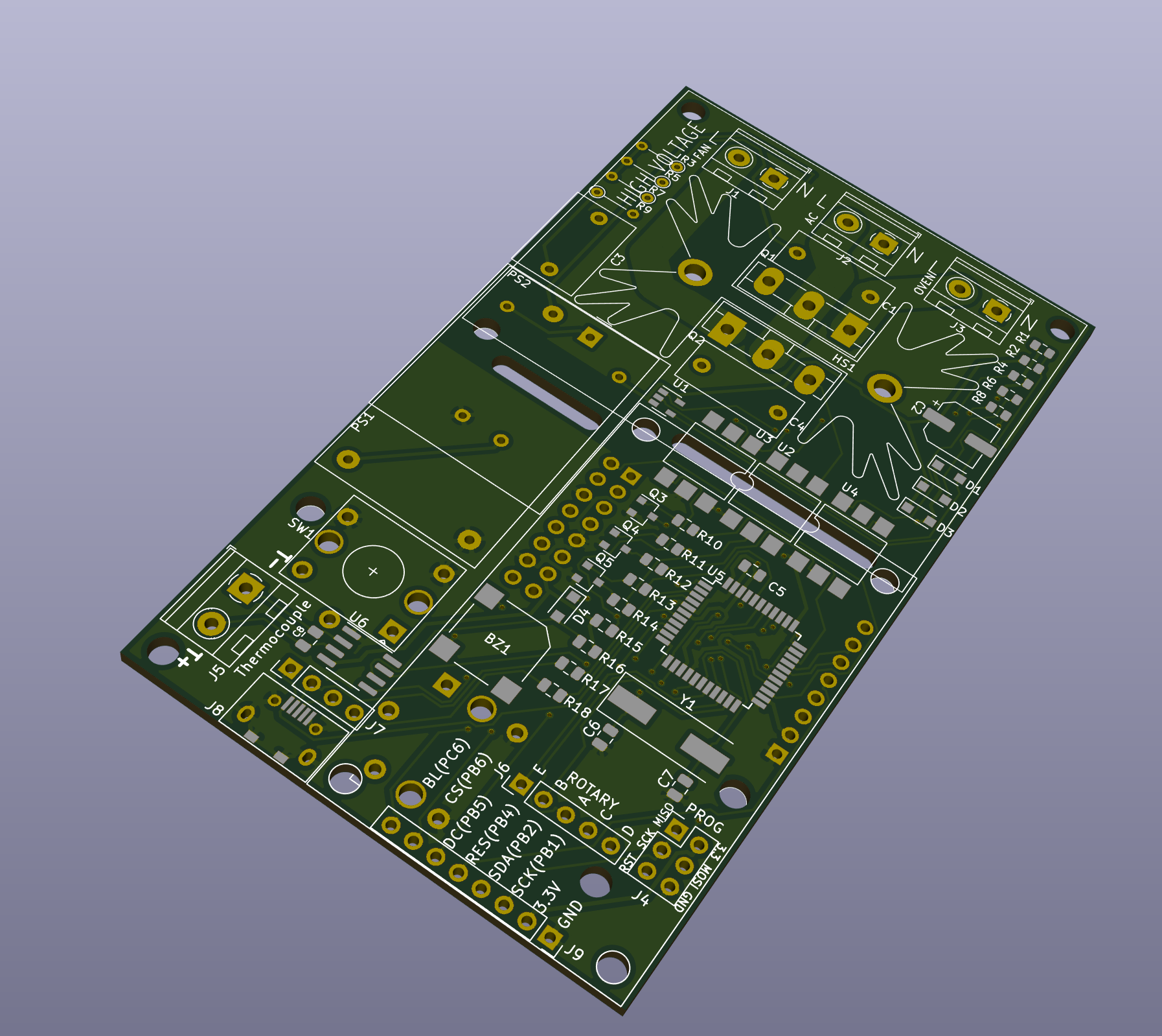
PCB design
I decided to go for a two layer board with the smallest possible footprint. I ended up fitting everything on 100mm x 57mm board. Since it's smaller than the standard 100mmx100mm limit on the usual PCB manufacturing sites (Elecrow, Seed, ITead etc), you can get 10 copies of the board produced for about US$5 + delivery. Personally I'm using the site called PCBWay.
The board enables you to connect the rotary encoder and the LCD either on top or on the bottom. There is an additional USB connector if you choose to solder the USB cable and not connect to the board connector directly.
The programming header is used to burn the initial bootloader into the MCU. After that firmware upgrades can be done using USB cable and Arduino IDE.
Both TRIACs are mounted on the same heatsink - the firmware will run either the Oven or the Fan, they are never used simultaneously. Using 25A for the Fan is a bit of overkill, but TRIACs are cheap, and it gives flexibility if you decide to connect something else to it.
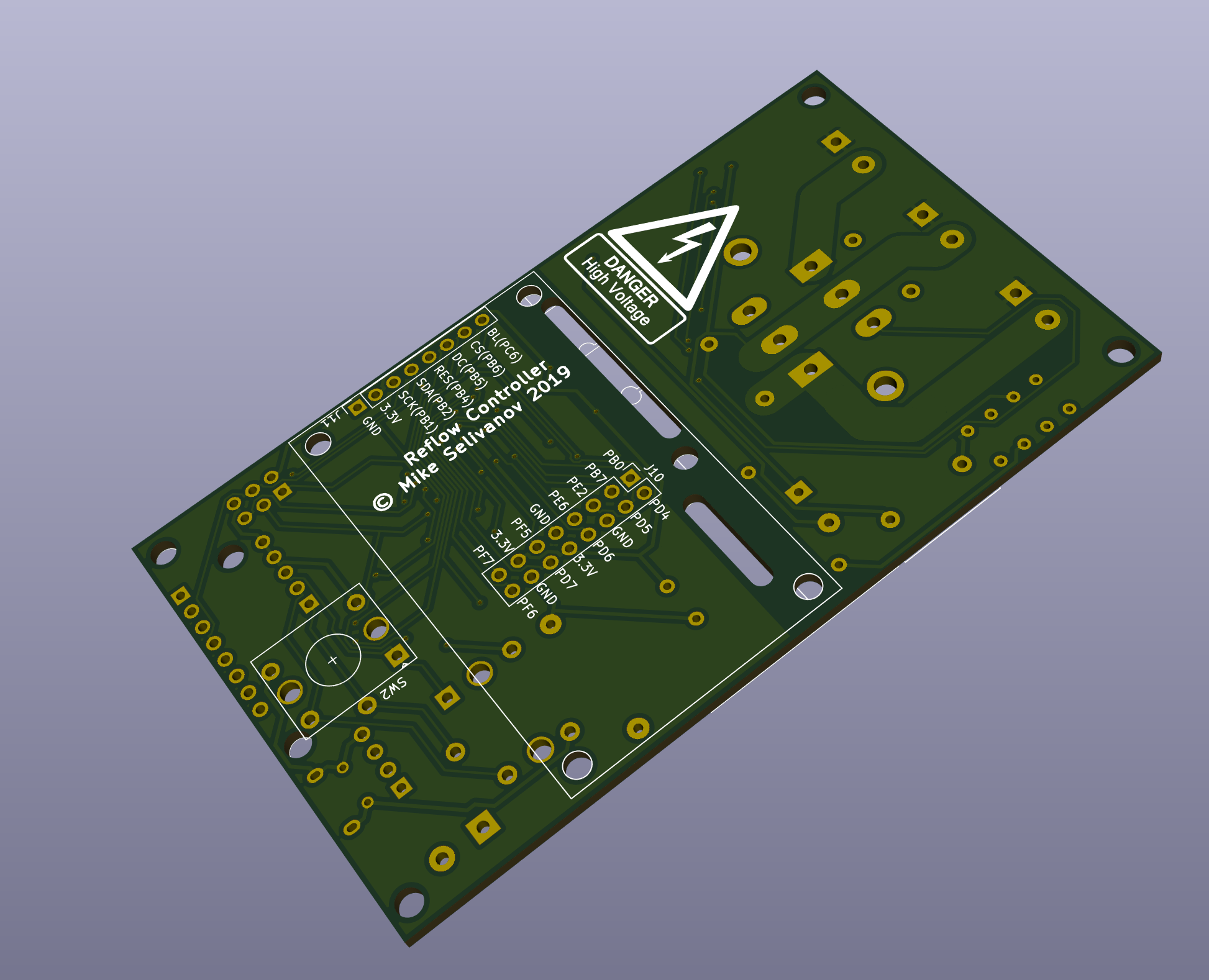
I laid out the PCB with the high side of the board marked off at the top. A warning legend on the silkscreen warns about the high voltage present in that area.
There is no absolute number for the width of a trace required to carry a given current across a PCB. Increasing the width of a trace will lower the electrical resistance and decrease the power loss and the heat generated.
According to on-line calculators that let you experiment interactively with your numbers, I settled on a trace width of 173mil * 2 (traces on both sides of the PCB) for the live trace which for an outer layer on 1oz copper conducting 16A would result in a 21°C worst case temperature rise for a power loss of 400mW.
The neutral trace is common for all three terminals. It's width is 100mil * 2. If you connect neutral to the PCB, keep the currrent under 10.5A for temperature rise under 20°C. If you want to use higher current, you can connect the neutral directly to the heating element/fan, bypassing the PCB.
There are standards for how close high voltage traces can get to other traces (creepage distance) that take into account the environment that the product will operate in (pollution level). You might be surprised at how low those minimums are; for this board 1.5mm would be enough. I leave more spacing than that and I also provide cutouts in the places where the high voltage areas come closest to low voltage.
The bottom and the top side of the board outside the high voltage area is filled and connected to the GND net.
Important safety note
The mains traces on the top of the board may run directly under the metal of the TRIAC heatsink. It will depend on the type of heatsink that you have chosen to use and it definitely happens with the heatsink that I have selected. The solder mask is the only thing preventing the heatsink becoming live, and of course solder mask is far from being an appropriate insulator for mains voltages.
To mitigate this issue, ensure that there is at least a couple of millimeters of air-gap between the bottom of the heatsink and the board when you solder the TRIAC into place. The large pins on the bottom of the heatsink fit into the board and can be soldered into place to totally prevent any movement.
As an alernative, insulate the base of the heatsink with electricians tape rated in excess of the AC peak voltage which is about 340V in the 220V/230V countries and 170V in the USA.
The firmware
The firmware for this device was compiled Arduino IDE 1.8.3 and can be cloned from gitlab. You can compile it from source or you can flash it directly to the MCU.
Flashing the bootloader
The bootloader can be uploaded directly to the MCU using a programmer connected to the J4 header using jumper wires. The pins are marked on the silkscreen.
Open Arduino IDE, select your programmer model (I use usbtiny), select the right board (Adafruit Circuit Playground) and choose “Burn Bootloader”.
After that, all firmware uploads can be done using the USB interface.
Flashing the firmware to the MCU
The firmware can be uploaded directly to the MCU using a USB cable.
You need to power the MCU, so flashing is done while the board is connected to the mains.
Select the right board in Arduino IDE (Adafruit Circuit Playground), open the sketch, build and upload to the controller.
Serial Output
During the reflow cycle the controller will output the reflow data in CSV format. All you have to do is connect the USB cable, open a serial terminal and copy the data into Excel after the reflow is complete.
You can also use Arduino IDE as a terminal.
User Interface
Main Menu
When you turn on the controller, you're welcomed with the main menu:
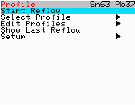
You have the option to start the reflow process, select the reflow profile, edit one of the profiles, show the last reflow data, and setup different configuration options.
The top header shows the current selected reflow profile.
The items with an arrow (triangle) are sub-menus.
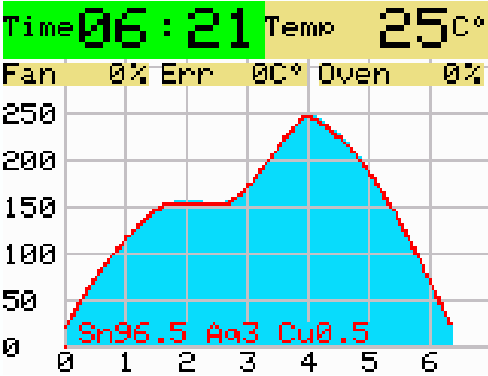
Start Reflow
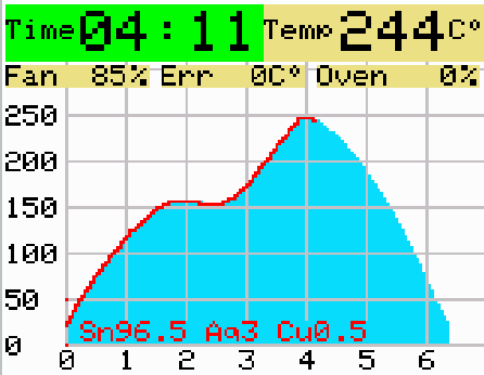
This option starts the actual reflow process. On the left upper corner you can see the elapsed time, on the right - the current temperature.
The next line shows the current Fan percentage, temperature error (desired vs actual), and the Oven percentage.
The blue graph shows the planned temperature over time. On the left of the graph there is a temperature scale, and on the bottom - time in minutes.
The red line shows the actual temperature on the timeline.
If the reflow process takes longer than expected, the graph will redraw, showing the history as well.
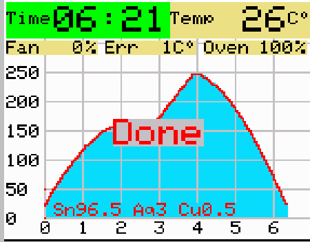
After the reflow is completed, it waits for a button press, while displaying the graph.
Select Profile
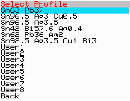
This option enables you to select the reflow profile.
Edit Profiles
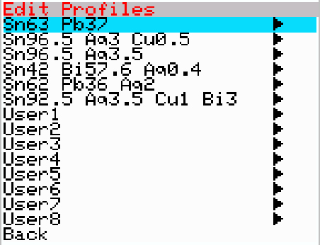
Using this option, you can modify any of the 14 profiles. Each profile stores all of the values for the parameters discussed earlier in this document.
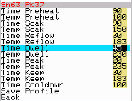
The time is in seconds, and the temperature is either in Celsius of Fahrenheit, depending on your settings. The temperature is stored internally in Celsius, so if you use Fahrenheit, you might see that the value you entered is not the value that was stored (+/- 1 degree)
Show Last Reflow
This option will show the results of last reflow/PID autotune session. It will wait untill you press the button to exit.
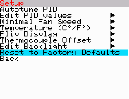
Setup
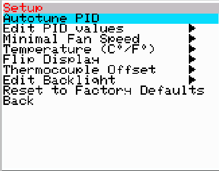
This menu enables you to configure miscellaneous parameters.
Autotune PID
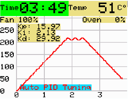
This option will run you Oven and try to automatically compute the right PID values. It will take several minutes to complete the procedure.
Edit PID values
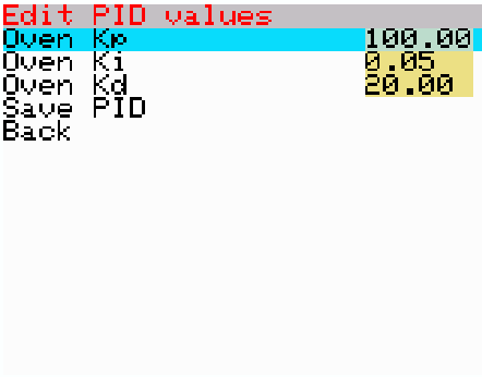
Here you can manually edit the PID values.
Minimal Fan Speed
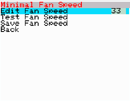
This is the minimal speed the fan starts turning. You can test the value using the "Test Fan Speed" option.
Temperature (C°/F°)
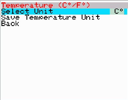
Select the display units. Regardless of your selection, internally everything is stored and calculated in degrees Celsius.
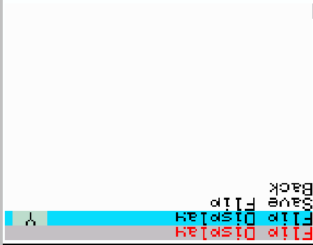
Flip Display
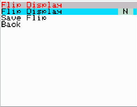
This option will flip the direction of the display - so you can mount the LCD using both directions (horizontally or upside-down).
Thermocouple Offset
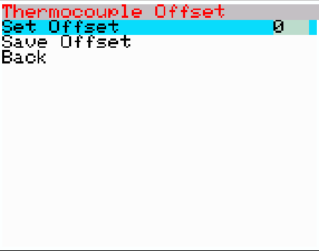
This option enables you to calibrate thermocouple offset. You can check the temperature using boiling water, or any other precise temperature source.
Edit Backlight
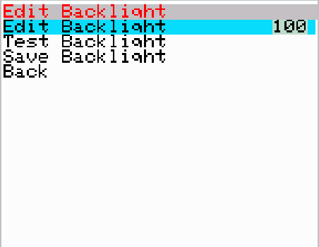
Backlight can be edited (the value is between 0-100%). You can test the value using the "Test Backlight" option.
Reset to Factory Defaults
Comments